

A tray can look intact while loose splices, blocked drainage holes, added cable weight, or a damaged cut edge quietly reduces its service life. By the end, you will have a practical inspection routine, a safe method for adding or recovering cables, and clear criteria for repair, replacement, or a different tray system.
Key takeaways
- Inspect after energising, cable work, construction, and severe monsoon exposure.
- Check tray corrosion, cable loading, support spacing, and bonding together.
- Add cables only after confirming fill, bend radius, weight, and sharp-edge protection.
- Isolate failed sections before documenting damage and restoring the route.
Set an inspection routine that matches the installation risk
Inspect perforated cable trays in Delhi on a risk-based schedule, not only by calendar date. Check every run before energising, after construction or cable work, and after severe monsoon exposure. Outdoor roofs, basements, shafts, wash-down areas, and traffic-polluted locations need closer attention than clean, dry electrical rooms.
Use this minimum cadence, then shorten it when defects or environmental exposure justify closer control:
- High-risk locations: inspect monthly during the wet season and quarterly afterward.
- Moderate-risk locations: inspect every three months.
- Clean, dry indoor rooms: inspect every six months, with an annual detailed review.
- Any tray struck, modified, overloaded, or exposed to flooding: inspect immediately before returning it to service.
A completed maintenance record must identify the exact run, not merely state “tray inspected.” Keep a dated entry containing:
- route or tray identification and location
- inspector’s name and inspection date
- photographs of joints, supports, field cuts, drainage holes, and cable condition
- findings on dust, water retention, corrosion, loose hardware, distortion, sharp edges, and cable sag
- cleaning performed and materials removed
- corrective-action number, responsible person, closure date, and next inspection date
Retain the tray layout, load information, repair instructions, and closed work order with these entries. A signed checklist without route identification, findings, or before-and-after evidence proves little.
Inspect the tray, cables, supports, and bonding as one system
Treat the first inspection as a system check, not a tray-only check. Confirm that supports are correctly spaced and anchored, cables remain accessible without crushing or tight bends, and protective bonding is continuous across every splice and section.
- Look for deflection, twisted side rails, displaced sections, and supports pulled from the structure.
- Check every splice for loose, missing, or incorrectly fitted hardware, especially near movement joints.
- Inspect field cuts for burrs and sharp edges; check whether any cable sheath bears against exposed metal.
- Clear blocked perforations and drainage holes, then look for standing water, dust-packed openings, and corrosion at joints or cut edges.
- Keep cable coils, tools, hoses, and other concentrated loads off the tray; they can create permanent deflection.
- Verify bonding jumpers, connection points, and continuity across painted or corroded joints.
- Check long runs for movement allowance. Rigidly locked splices can transfer building movement into supports, joints, or cables.
Classify a finding as urgent when it can cause shock, fire, cable damage, or collapse before the next planned visit. Isolate the affected circuit and support the cables independently for exposed conductors, damaged insulation, severe sag, a failing support, a tray carrying excessive load, or a sharp edge touching a cable.
Repair loose hardware, blocked drainage, early corrosion, or minor deflection promptly, but escalate if the defect is spreading or the manufacturer’s load or span table is no longer met. Restore expansion and bonding arrangements to the manufacturer’s instructions and the design standard.
Add cables without overloading or damaging the existing run
Before you pull a new cable, verify the tray’s remaining capacity, support condition, ventilation space, and access route. Width alone proves nothing: capacity depends on tray material, section, support span, splice arrangement, orientation, and the cable weights shown in the manufacturer’s load table.
- Inventory the existing and proposed cables, recording outside diameter, weight, route, and minimum bend radius from each cable datasheet.
- Check the tray load table at the actual support spacing, then include the added cable weight and any approved future allowance. If capacity is inadequate, install an independently supported tray section rather than loading the old run further.
- Keep perforations open and leave room to lift cables out for inspection. Do not pack new circuits tightly against covers, block ventilation openings, or bury existing cables beneath an unmanageable bundle.
- Route the new cable without forcing a bend tighter than its specified minimum radius. Use approved supports at changes of direction and near tray ends so the cable does not sag onto sharp edges or splice plates.
- Secure temporary coils, tools, hoses, and pulling equipment independently. A perforated tray is not a walkway, ladder, or support for other equipment.
Maintain access to every cable identification point and splice. If side rails are buckled, welds are cracked, supports have failed, or section loss is severe, replace the section; straightening it in place does not restore certified capacity without design approval.
On long runs, preserve the manufacturer’s expansion-joint and bonding arrangement instead of locking every splice rigidly.
Use a controlled recovery sequence when the tray has failed
Stop adding cables and remove temporary loads before starting perforated cable tray recovery. Isolate affected circuits where the work could disturb insulation, then support every cable independently with slings or temporary supports; never let cable weight hang from a damaged section.
- Photograph and tag the run, record cable inventory, and mark displaced, overloaded, corroded, or partly dismantled sections.
- Check tray width, material, support spacing, splice arrangement, cable fill, bend radius, and load against the manufacturer’s tables. Keep cable coils, tools, hoses, and other concentrated loads off the tray.
- Clean localized corrosion, prepare the steel, and repair field-cut or damaged galvanizing with a compatible zinc-rich coating under ASTM A780. Do not paint over dirt or oil.
- Replace missing or deformed splice hardware, and add independently supported tray sections when capacity or access is inadequate.
- Replace sections with distorted side rails, cracked welds, severe section loss, or failed supports. Do not straighten a permanently buckled tray in place unless the design authority approves the repair and confirms capacity.
- Reinstall cables without forcing a manufacturer’s minimum bend radius, then verify support, bonding, clearances, and fastener torque before returning circuits to service.
For repeated failure, compare the damage with inspection records and construction changes. Check whether support spans changed, anchors loosened, water remains in the run, corrosion matches the environment, or later cable additions exceeded the load table. Confirm that no one used the tray as a walkway, ladder, or support for other equipment.
Document the cause, corrective action, photographs, and final approval.
Choose the finish and supplier information for the actual environment
A tray that survives Delhi’s roof, basement, or wash-down conditions starts with the right material, finish, and form. Ladder tray is a construction type, not a finish; it improves access and ventilation but leaves cables less protected from falling debris and impact.
| Option | What it means | When it applies |
|---|---|---|
| Galvanized steel | Zinc-coated steel with strong mechanical performance; cut edges and trapped moisture need attention | General indoor, outdoor, and utility installations when drainage is good |
| Painted steel | Steel protected by a paint or powder-coat system; scratches expose the substrate | Clean, dry interiors where impact and standing water are controlled |
| Stainless steel | High corrosion resistance with higher material cost; select the grade for the chemical exposure | Coastal, chemical, food-processing, or persistent wash-down areas |
| Aluminium | Lightweight and corrosion-resistant, with lower mechanical stiffness than steel | Roofs, long access routes, or installations where handling weight matters |
| Ladder tray | Rungs replace most of the perforated base; cables remain easy to inspect but less enclosed | Large cables, heavy runs, and routes needing frequent access |
For perforated cable trays for maintenance in Delhi, ask a perforated cable tray supplier in Delhi for one complete submittal, not a quotation showing only width, height, and thickness. Request:
- Material, coating or paint system, section dimensions, and permissible support spans
- Load tables for the specified width, material, support spacing, and splice arrangement
- Splice hardware, bonding provisions, and continuity details
- Field-cut repair instructions plus test or inspection records
Keep cable coils, tools, and temporary hoses off every tray; support those loads independently. D And D Metal can be compared on this same evidence rather than on tray dimensions alone.
Related products
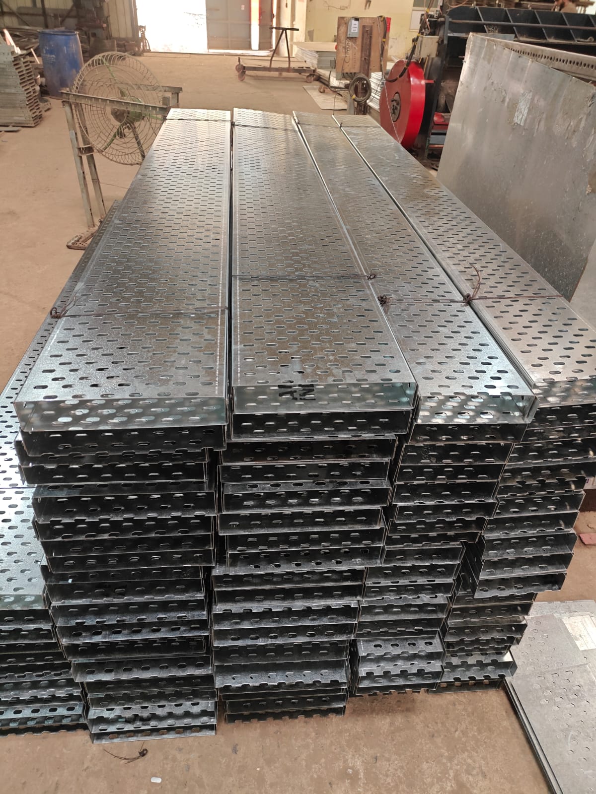 | Cable Tray Perforated Type Cable Trays are a popular choice for supporting and managing electrical wires in various installations. View product → |
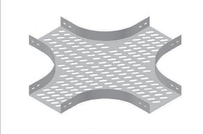 | Perforated type cable tray Cable Tray Perforated Horizontal Cross A perforated horizontal cross for cable trays is a connector used in cable management systems. View product → |
Frequently asked questions
How often should you inspect perforated cable trays in Delhi?
Inspect each run before energising, after construction or cable work, and after severe monsoon exposure. Increase inspection frequency in outdoor roofs, basements, shafts, wash-down areas, and traffic-polluted locations.
What should you check during a cable tray inspection?
Inspect the tray for corrosion, deformation, sharp edges, loose fasteners, and blocked perforations. Check cable spacing and support, then verify bonding jumpers, earth continuity, and connection to the protective earthing system.
How can you add cables without damaging an existing perforated tray?
Confirm the tray’s usable fill, cable weight, support capacity, and bend-radius requirements before installation. Protect cables from sharp edges, avoid dragging them across existing conductors, and secure them without crushing insulation.
What is the correct response when a perforated cable tray fails?
Make the circuit safe, isolate or support the affected section, record the failure, and inspect connected cables and supports. Replace damaged tray or fittings, restore bonding, and test the route before re-energising.
How should you choose a perforated cable tray finish for Delhi conditions?
Match the finish to exposure: use a finish rated for indoor dry rooms, and select stronger corrosion protection for monsoon-exposed, damp, polluted, or wash-down locations. Ask the perforated cable tray supplier in Delhi for coating details, material thickness, load data, and installation guidance.
Related products
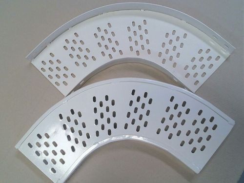 | Perforated type cable tray Cable Tray Perforated Horizontal Elbow A perforated horizontal elbow for cable trays is a fitting used to change the direction of cable tray systems, typically at a 90-degree angle. View product → |
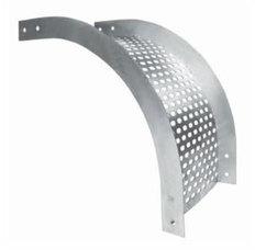 | Perforated type cable tray Cable Tray Perforated Vertical Elbow Down A perforated vertical elbow down in a cable tray system is designed to redirect cable pathways in a vertical direction. View product → |
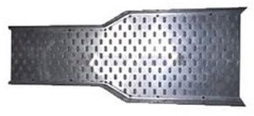 | Perforated type cable tray A cable tray perforated reducer is a fitting used in cable management systems. View product → |
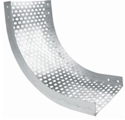 | Perforated type cable tray Cable Tray Perforated Vertical Elbow Up A perforated vertical elbow up for a cable tray is a fitting used to change the direction of cable trays in a vertical orientation. View product → |
Keywords