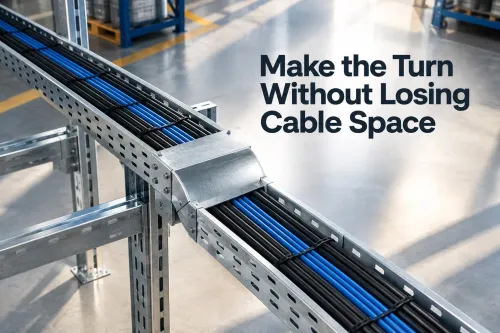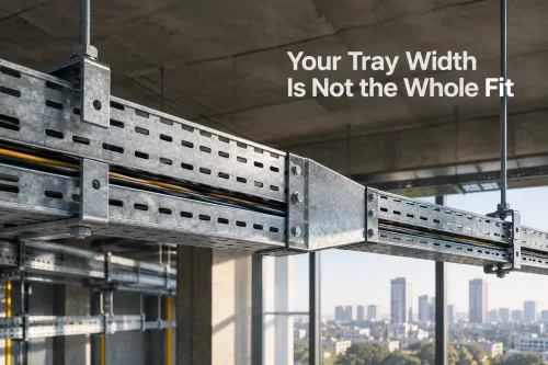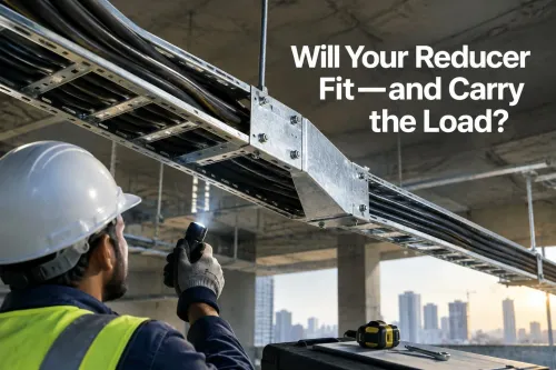
A vertical elbow can connect a tray route at a riser, shaft, plant-room entry or equipment connection and still create cable damage, access problems or an unapproved load condition if it is specified only as “90-degree.” By the end, you will know how to define the orientation, radius, dimensions, support system, finish and installation details needed to compare and order the correct fitting for a Delhi construction project.
Key takeaways
- Choose up or down orientation from the elevation, not the plan view.
- Match elbow width and radius to the tray and largest cable bend radius.
- Specify tray dimensions, material, finish, supports, joints and bonding in the RFQ.
- Coordinate the elbow location, orientation and access space before installation.
Choose the Correct Up or Down Orientation at the Route
Read the route in elevation from the incoming tray run: choose a vertical elbow up when the tray must turn toward a higher level, and choose a vertical elbow down when it must turn toward a lower level. Do not judge orientation from the plan view; identical width and angle dimensions can conceal opposite fittings.
| Orientation | Route change | Typical location |
|---|---|---|
| Up | Incoming tray rises after the turn | Floor-to-floor riser, overhead tray entering a higher shaft opening, or equipment connection above the approach level |
| Down | Incoming tray falls after the turn | Tray dropping into a lower plant room, floor penetration, or equipment connection below the approach level |
Mark the incoming run, the required destination elevation, and an arrow labelled UP or DOWN on the elevation drawing. Show the arrow relative to the incoming tray, because “vertical elbow up” and “vertical elbow down” are not interchangeable purchasing descriptions. A supplier viewing the fitting from the opposite side can otherwise quote the wrong orientation.
Before approval, compare the fitting’s handedness, support points, cover clearance, cable-entry opening and connection-hole pattern with the shaft or equipment layout. Request a dimensional drawing showing overall length, tangent lengths and centre-line radius.
For an RFQ using the phrase cable tray perforated for vertical elbow in delhi, state the orientation beside the tray width, angle and mating tray profile; never leave “perforated vertical elbow” as the complete description.
Match the Fitting to Tray Dimensions and Cable Bend Radius
Fit the elbow to the tray profile and the cable’s minimum bend radius, not to tray width alone. Confirm the tray’s nominal width, usable side-rail height, sheet thickness, material grade, surface finish, and mating profile before approval.
| Measurement or cable data | What to verify | Failure if ignored |
|---|---|---|
| Width and side-rail height | Elbow matches the tray’s internal clear dimensions | Cables foul the rails or the joint will not close |
| Angle, inside radius and centre-line radius | Radius meets the largest cable’s minimum bend radius | Power, control or fibre cables kink or exceed manufacturer limits |
| Overall length and tangent lengths | Fitting clears shafts, penetrations and equipment | The route collides with walls or leaves no straight entry |
| Connection-hole pattern and orientation | Handedness, up/down direction and mating holes match | Sections arrive reversed or cannot be bolted together |
| Cable outside diameter and quantity | Check actual bend fill at the inside and outside of the curve | Cables crowd despite acceptable straight-tray fill |
| Cover dimensions | Specify matching elbow cover, overlap, fixings and access | A straight cover leaves cable exposed at the bend |
Ask for a dimensional drawing showing all these measurements, plus support recommendations. A “perforated vertical elbow” alone is not interchangeable: a perforated cable tray vertical elbow up in Delhi and a perforated cable tray vertical elbow down in Delhi can need different support positions and cable-entry clearances.
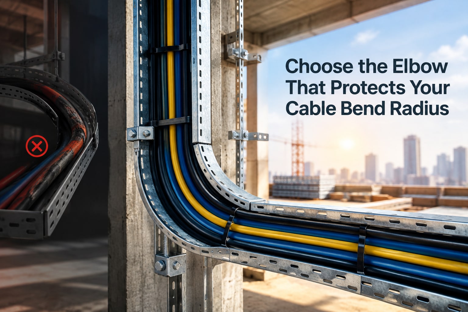
Check the manufacturer’s minimum radius for each cable type. Heavy or large-diameter cables may need cleats, clamps or added supports; perforations and cable ties do not replace restraint through the turn.
Decide Between a Perforated Elbow and Other Vertical Routing Methods
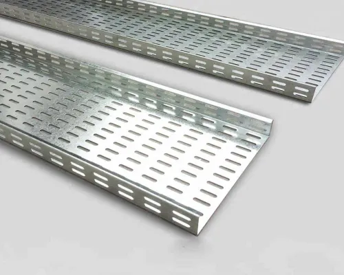
A perforated vertical elbow is the better choice for a defined 90-degree rise or drop where cables need continuous support through the turn, protection from nearby steelwork, and a predictable bend radius. It suits risers, shaft entries, plant-room transitions, floor penetrations and equipment connections better than improvising a bend on site.
| Option | What it provides | When it applies |
|---|---|---|
| Perforated vertical elbow | Continuous base and side support with factory-formed geometry | Choose it for grouped power, control, instrumentation or communication cables that need containment through a full vertical turn |
| Ladder elbow | Open rungs, stronger ventilation and easier cleat installation | Choose it for large, heavy or heat-sensitive power cables when cable cleats and airflow matter more than a solid base |
| Field-fabricated bend | A site-made transition from straight tray | Use only for an engineered exception; poor cutting or welding can reduce strength, damage galvanizing and violate the cable bend radius |
| Vertical offset | A short change in elevation rather than a full turn | Choose it to clear a beam, pipe or doorway without routing cables through a 90-degree riser |
| Separate tray sections | Two straight pieces joined with fittings or supports | Use it where access, transport or a discontinuous route justifies extra joints and support points |
Select a perforated elbow when the cable must remain contained and the route geometry is repeatable. Reject it when the bend crowds cables, blocks cleat access or cannot meet the manufacturer’s minimum radius.
For vertical cable tray fittings in Delhi, state “up” or “down” from the incoming run, show an elevation arrow, and specify the mating tray profile. A connected-looking fitting can still be the wrong orientation or radius.
Design Supports, Joints, Bonding and Cable Restraint
Support the elbow as a load-bearing change of direction, not as a short tray offcut. Place a bracket or trapeze close to each elbow end, then check the manufacturer’s span and load table for an intermediate support. The bend concentrates cable weight and longitudinal pull at the joints.
Up and down fittings can need different support positions and cover clearances, so show the elevation arrow from the incoming tray run.
Use only the splice plates, couplers, bolts and washers specified for the tray system. A tight-looking connection through paint or hot-dip zinc does not prove mechanical capacity or electrical continuity. Mixing hardware from another system can misalign rails, reduce joint strength and interrupt bonding.
Make the installation sequence explicit:
- Set the elbow and adjoining tray on independent supports before pulling cable; do not leave the fitting hanging from cable weight or from one joint.
- Bolt every connection fully, keep perforations aligned, and inspect for rail distortion or sharp edges that could damage insulation.
- Install bonding jumpers across joints wherever the project earthing design requires metallic continuity. Test continuity after assembly and record the result against the project’s specified limit.
- Restrain cables near the entry, exit and turn with cleats or approved ties sized for the cable type and fault forces. Maintain the manufacturer’s minimum bend radius and spacing; short-radius turns can press cables against the side rail.
For a perforated cable tray vertical elbow down in delhi, confirm these details on the elevation and purchase order, not only in a catalogue title.
Write a Delhi-Ready RFQ and Coordinate the Fitting on Site
Put the order and approval record on the same dimensional evidence. For a cable tray perforated for vertical elbow in delhi, “90-degree elbow” is not enough to prevent a wrong fitting.
1. State the incoming tray width, usable side-rail height, sheet thickness, material grade, surface finish, load class and required bend angle. Name IEC 61537 as the product standard where it governs the project, then add the project corrosion-protection, testing and inspection requirements.
2. Mark “vertical elbow up” or “vertical elbow down” relative to the incoming run, and attach an elevation arrow. Do not rely on plan view: up and down versions can differ in support points, cover geometry and cable-entry clearance.
3. Require the supplier’s drawing before approval. Check overall length, tangent lengths, centre-line radius, inside bend radius, handedness, mating-tray profile, connection-hole pattern and recommended supports against the shaft, floor penetration or equipment connection.
4. Record cable data beside the drawing: largest outside diameter, minimum bend radius and separation requirements for power, control, instrumentation, fibre-optic and communication cables. Reject an elbow that forces any cable below its specified radius.
5. Specify matching covers separately, including cover type, overlap, fixing method, access points and protection at both sides of the bend. A straight cover cut to length is not a fitting cover.
6. During inspection, photograph orientation, dimensions, joints, fasteners, supports, bonding links, finish damage and cable clearance; record drawing revision, batch or delivery reference and deviations. For vertical cable tray fittings in delhi, D And D Metal can use this signed checklist to resolve a quoted fitting against the installed route rather than a catalogue name.
Related products
 | Perforated type cable tray Cable Tray Perforated Vertical Elbow Down A perforated vertical elbow down in a cable tray system is designed to redirect cable pathways in a vertical direction. View product → |
 | Ladder cable tray Cable Tray Ladder Vertical Elbow Down A cable tray ladder vertical elbow down is a component used in cable management systems. View product → |
Frequently asked questions
How do you choose a perforated cable tray vertical elbow up or down in Delhi?
Read the route in elevation from the incoming tray run. Select an elbow up for a turn toward a higher level and an elbow down for a turn toward a lower level.
How do you match a vertical elbow to the tray and cable bend radius?
Confirm the tray width, side-rail height, material and angle, then select an elbow whose inside radius meets the largest cable manufacturer’s minimum bend radius.
When is a perforated elbow preferable to another vertical routing method?
Use a perforated elbow when the tray route needs a defined vertical turn with accessible cable support. Compare it with risers, separate vertical trays and field-fabricated transitions when space, cable access or bend radius makes the elbow unsuitable.
What must a Delhi-ready RFQ include for vertical cable tray fittings?
State the up or down orientation, tray dimensions, angle, inside radius, material and finish, load, support spacing, joint hardware, bonding method, cable restraint and delivery or site-coordination requirements.
Related product
 | Perforated type cable tray Cable Tray Perforated Horizontal Cross A perforated horizontal cross for cable trays is a connector used in cable management systems. View product → |
Keywords