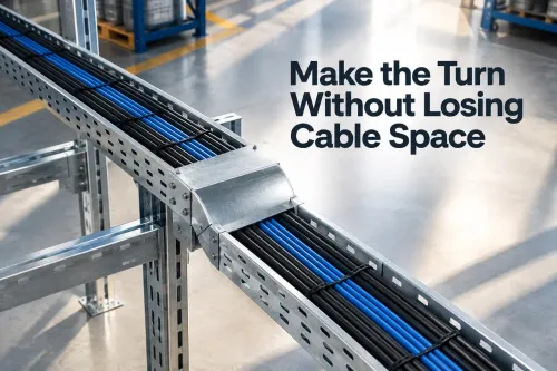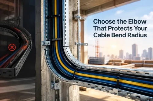

A reducer that matches only the tray width can still fail at the site because its side profile, splice holes, orientation, support span, and cable bend path are wrong. You will be able to prepare a quotation-ready specification, check the transition against the cable route, and decide when a perforated reducer is unsuitable.
Key takeaways
- Specify both tray widths, rail height, thickness, finish, length, and bend radius.
- Match the reducer’s flange and side-rail profile to the installed tray system.
- Verify cable fill, bend radius, supports, and bonding across the transition.
- Reject a reducer when a junction box or custom transition is safer.
Specify the reducer geometry before you request a price
Define the complete geometry before asking for a cable tray reducer for contractors. “300 mm to 150 mm perforated reducer” is not a complete fabrication description: specify large-end and small-end widths, side-rail height, flange profile, sheet thickness, material, finish, reducer length, bend-radius requirement, and straight-run lengths.
Submit a dimensioned plan or elevation drawing. Define left and right from a named view, such as looking in the direction of cable travel from the large end, and mark the number and location of splice joints, support points, and distances to panels, transformers, junction boxes, and gland plates.
- Concentric: both tray centre lines remain aligned.
- Left-hand or right-hand: the width reduction shifts to one side.
- Offset: the route moves around a column, beam, pipe, or equipment connection.
Show whether the fitting must preserve a particular cable centre line or gland alignment. For a search such as “perforated cable tray for reducer Gurgaon,” do not assume the phrase defines a standard geometry.
| Orientation | Physical result | Drawing requirement |
|---|---|---|
| Concentric | Centre lines align | Show both tray axes |
| Left-hand | Reduction shifts left | State viewing direction |
| Right-hand | Reduction shifts right | State viewing direction |
| Offset | Route avoids an obstruction | Dimension offset and obstruction clearance |
Match the reducer to the actual tray system, not its nominal width
A 450 mm tray from one series will not automatically accept a 450 mm reducer from another. Before releasing the purchase order, ask the supplier to name the approved tray manufacturer or series and compare the reducer against a physical straight-tray sample or approved drawing.
| Check | Straight tray | Reducer confirmation |
|---|---|---|
| Side profile | Side-rail shape, height, flange geometry | Same profile and mating flange |
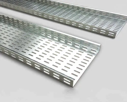
| Openings | Perforation pitch and hole dimensions | Matching pattern without blocked holes |
| Jointing | Splice-hole positions and effective internal width | Correct coupling plates, bolts, nuts, washers, and splice connectors |
| Strength | Manufacturer’s span, deflection, and load data | Separate allowable span, deflection, and loading data |
Request a dimensioned drawing and a fitting schedule from any perforated cable tray reducer supplier Gurgaon. The schedule should list each piece by size and finish:
- Concentric, left-hand, right-hand, and custom offset reducers
- Covers, separators, bonding jumpers or bonding hardware
- Splice kits, connectors, and support brackets
Do not transfer the straight-tray load rating to the reducer without written confirmation. Missing accessories often become drilled, cut, or improvised field modifications.
State the coating precisely: pre-galvanized sheet or hot-dip galvanizing after fabrication. Specify the zinc-rich repair method for drilled, cut, enlarged, or damaged edges; “GI finish” is insufficient. Apply the same evidence standard when comparing perforated cable tray fittings Gurgaon, not merely their nominal width.
Check cable fill, bend radius, support, and bonding at the transition
A reducer can create a failure point by crowding cables at the narrow end, forcing a bend, or leaving a splice joint carrying cable weight. For a cable tray reducer for contractors, inspect the transition as part of the complete route, not as a harmless change in width.
1. Calculate the cable bundle at both ends. Include future capacity, separators, single-core spacing, and the project’s specified fill rule. Do not compress cables into the narrow end or apply one universal fill percentage.
2. Check every power, control, armoured, and medium-voltage cable against the manufacturer’s minimum bend radius. A short reducer is not a bend-radius fitting; use a longer custom transition or a separate bend arrangement when the cable cannot turn within the supplied length.
3. Support the reducer using its own span and loading information. Place supports close enough that a splice joint does not carry unsupported cable weight, especially where heavy armoured or medium-voltage cables cross the transition.
4. Deburr cut edges and install grommet or edge protection where cables could touch perforations. Maintain separator continuity between power and instrumentation or communication cables, and verify the project’s required separation at the narrow end.
5. Test electrical continuity across splice plates and bonding hardware after assembly. Paint or zinc coating can interrupt metal-to-metal contact, so install the specified bonding jumper or hardware and record the continuity result where the tray forms part of the protective-bonding system.
Decide when a perforated reducer is the wrong site solution
Choose a standard perforated reducer only when the route changes width and the tray environment, cable size, and bottom construction suit perforation. It is a poor choice outdoors or in washdown areas requiring greater ingress protection, for small control cables that could fall through large openings, or for systems requiring a continuous solid bottom.
| Option | What it means | When it applies |
|---|---|---|
| Standard perforated reducer | Factory-made taper with matching holes and documented finish | Normal width transition on a compatible tray system |
| On-site tapered section | Site measuring, cutting, drilling, deburring, coating repair, and inspection | Emergency work or a simple route where a standard fitting cannot be obtained |
| Custom section or another construction | Purpose-built geometry or solid-bottom tray | Unusual offset, gland alignment, large cable bend radius, separator continuity, or higher ingress protection |
Site fabrication adds another opportunity for a misaligned joint. A factory-made reducer offers a controlled taper, matching holes, and repeatable dimensions, but it is not automatically better for an unusual route.
A reducer changes width, not elevation or direction. Use a vertical inside or outside bend, horizontal bend, tee, cross, or offset fitting when the coordinated layout requires one. Confirm the route before fabrication so the fitting does not block gland access.
When comparing perforated cable tray fittings Gurgaon suppliers, specify the route and failure condition, not just “reducer.” A standard fitting is the wrong answer if the cables cannot maintain bend radius or the tray construction cannot protect them.
Build a Gurgaon purchase package that can be checked at delivery
Send the perforated cable tray reducer supplier Gurgaon a controlled purchase package, not the phrase “300 mm to 150 mm reducer.” Include:
- Approved tray manufacturer or series, route drawing, large- and small-end widths, side-rail height, flange profile, material, sheet thickness, finish, reducer length, bend-radius requirement, straight-run lengths, support span, cable schedule, separator requirements, and every splice location.
- Define left and right by a drawing convention: looking in the direction of cable travel from the large end. This prevents a mirror-image fitting.
- Request a fitting schedule listing straight, concentric, left-hand, right-hand and offset reducers; bends, tees, crosses, covers, separators, splice kits, bonding hardware, and supports by size and finish.
| Orientation | Geometry | Use |
|---|---|---|
| Concentric | Centre lines remain aligned | A straight-width transition |
| Left or right | Reduction stays against one tray side | A route aligned to a wall or equipment edge |
| Offset | Transition shifts around an obstruction | A column, beam, pipe, or gland connection |
At delivery, compare stamped or tagged dimensions with the approved drawing. Mate the reducer to straight tray and check flange shape, perforation pitch, splice-hole alignment, coupling plates, bolts, nuts, washers, and connectors. Reject sharp edges and record coating damage before installation.
Confirm the reducer’s allowable span, deflection, and loading data; never transfer the straight-tray rating automatically. D And D Metal should be evaluated on this evidence, supplying coordinated customer-specified fittings rather than quoting a nominal width for a perforated cable tray for reducer Gurgaon.
Frequently asked questions
What information should you provide when pricing a perforated cable tray reducer?
Provide the large-end and small-end widths, side-rail height, flange profile, sheet thickness, material, finish, reducer length, bend-radius requirement, and required straight-run lengths.
Why must a reducer match the actual tray system rather than its nominal width?
Two trays with the same nominal width can have different rail heights, flange shapes, perforation patterns, thicknesses, and joining methods. Confirm the physical profile and connection details before ordering.
What should you check at a cable tray reducer transition?
Check cable fill, minimum bend radius, support spacing, mechanical fixing, and electrical bonding. Confirm that cables do not press against cut edges or lose support at the narrowing point.
When is a perforated cable tray reducer the wrong site solution?
Use another arrangement when the width change is too abrupt, the cable bend radius cannot be maintained, the transition needs access for splicing, or the reducer cannot be supported and bonded reliably.
What should a Gurgaon purchase package include for delivery inspection?
Include an approved drawing, dimensions, material and finish, quantity, tray-system reference, hole pattern, fixing details, inspection criteria, and photographs or measurements to verify the delivered fittings.
Keywords