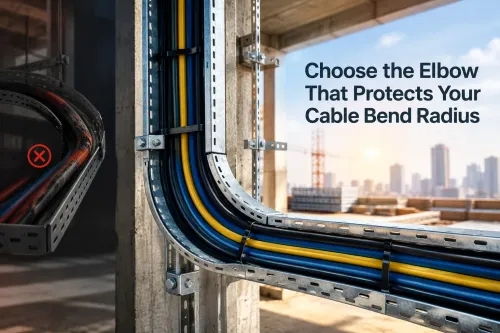
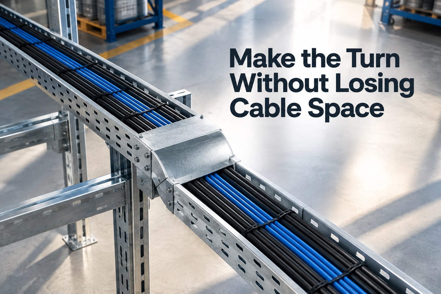
A route that turns around a column, plant room, or access corridor needs more than a curved piece of tray: the fitting must match the route plane, cable bend radius, tray dimensions, load, and joining method. By checking those points in order, you can select the correct elbow, avoid improvised site modifications, and install the change without creating a new pulling or maintenance problem.
Key takeaways
- Use a horizontal elbow for same-level direction changes, not rises or drops.
- Specify direction, radius, tray width, side rail height, and material.
- Check cable fill, bend radius, joint compatibility, and support loads before ordering.
- Keep tray sections aligned and bond or bridge joints where continuity requires it.
Identify the Route Change Before Choosing the Fitting
Trace the route in plan and elevation before selecting a fitting. If the tray changes direction while staying at approximately the same elevation, specify a horizontal cable tray route change fitting. A rise or drop requires a vertical inside or outside elbow, not a horizontal elbow.
| Option | What it means | When it applies |
|---|---|---|
| Horizontal elbow | Turns the tray left or right in plan | Use for a continuous direction change, such as 30°, 45°, 60°, or 90° |
| Horizontal tee | Adds one branch at the same elevation | Use where one tray run splits into two |
| Horizontal cross | Adds two branches at the same elevation | Use where four tray directions meet |
| Vertical elbow | Changes elevation while turning the route | Use for a rise, drop, inside bend, or outside bend |
| Field-fabricated offset | Cut and re-form or join tray sections on site | Use only when no standard fitting matches the route and clearance |
Mark the approach and departure directions, elevation, turn angle, inside or outside orientation, and clear space around the bend on the drawing. Compare that geometry with standard fittings before approving an offset. A factory-made fitting controls the radius and avoids sharp cut edges, improvised splices, and alignment problems.
If site fabrication is unavoidable, preserve the cable’s minimum bend radius, deburr every cut, protect exposed metal from corrosion, and use the approved joining hardware.
Specify the Elbow’s Direction, Radius, and Dimensions
Give the elbow’s direction, bend radius, and full mating dimensions—not merely its angle—so the fitting can be checked against the route drawing and the cable’s minimum bend radius. A horizontal elbow keeps the tray at approximately the same elevation; show any rise or drop separately.
For a cable tray horizontal elbow for route changes in Delhi, put these details on the drawing and purchase request:
- Tray width, side-rail height, flange profile, material, finish, and straight-section series
- Bend angle, such as 30°, 45°, 60°, or 90°, plus the inside radius and, if available, the outside radius
- Plan-view direction: approach line, departure line, clockwise or counterclockwise turn, and whether it is an inside or outside turn
- Elevation, centreline dimensions, available wall and ceiling clearance, and the minimum free space around the fitting
- Splice-hole pattern, joining hardware, and the exact dimensions where the elbow meets each straight tray
- The largest cable’s manufacturer-specified minimum bend radius, along with the required load and support span
Use a plan and side elevation with arrows for cable travel and dimension lines from fixed columns, walls, or equipment. Select an elbow radius at least equal to the most restrictive cable’s required bend radius; a tighter fitting can damage conductors or increase pulling tension.
Ask for a dimensional drawing before ordering, because two elbows with the same width and angle can have different radii, usable space, and splice geometry.
Check Cable Space, Tray Compatibility, and Support Loads
A route change can fit the drawing and still fail during cable installation. Confirm the elbow and straight sections as one loaded system, not as separate metal parts.
- Match the tray width, side-rail height, flange profile, splice-hole pattern, and joining hardware. Do not assume a 300 mm straight tray accepts every 300 mm elbow.
- Check the largest cable’s manufacturer-specified minimum bending radius against the elbow’s inside radius. A tighter bend can damage insulation, increase pulling tension, or force the cable outside its permitted bend.
- Recalculate usable cable area or loading under the governing code and project specification. The elbow’s curved geometry can reduce clear space and crowd cables even when the straight tray passes its fill check.
- Review the pulling method, cable weight, pulling tension, sidewall pressure, and access for rollers or guides. A hand-laid control cable and a mechanically pulled power cable do not impose the same demands.
- Provide supports close to both sides of the elbow. Do not use the elbow, splice plates, or their bolts to bridge an unsupported gap; verify spacing against the elbow’s tested load data, not only the straight tray span.
- Order compatible splice plates, bolts, bonding provisions, and instructions as a complete cable tray elbow for contractors. Missing hardware leads to field drilling, misalignment, and delayed cable installation.
- For galvanized outdoor or industrial tray, match the elbow and hardware’s corrosion protection and treat every field-cut edge.
Record these checks on the layout and purchase order before release. That record exposes a mismatch while changing the fitting is still cheaper than moving installed cable.
Install the Bend Without Losing Alignment or Continuity
Keep the elbow on the drawn centreline and at the specified elevation before tightening any splice. Dry-fit both straight tray sections, check the inside and outside edges against the plan, and confirm that every splice hole aligns without forcing the rails sideways.
Use this installation check:
- Confirm the elbow width, side-rail profile, rung pattern, and splice-hole pattern match the adjoining tray.
- Place a support close enough to the bend to keep the elbow within the manufacturer’s rated span and load limits.
- Tighten the approved splice plates and bolts, then fit bonding jumpers where the joint design requires them.
- Remove paint, rust, or dirt from bonding contact areas and test electrical continuity across the joint.
- Inspect every cut edge for burrs, exposed corners, or bolt tips that could damage cable insulation.
- Check the cable’s minimum bend radius through the turn; a correctly aligned tray does not make an overly tight cable bend safe.
Do not leave the elbow hanging from one straight section while the other remains unsupported. That twists the splice and can open a gap at the rail.
A factory-made elbow avoids most field-cut edges. If cutting is unavoidable, deburr the edge, install an approved edge protector, seal the exposed metal with a compatible zinc-rich repair coating, and prevent contact between incompatible metals that could accelerate galvanic corrosion.
A request saying “cable tray horizontal elbow in delhi” is not enough for installation control. Record the final orientation, radius, support location, bonding method, and coating repair before cable pulling begins.
Order the Complete Assembly From a Suitable Supplier
Do not compare quotations by elbow price alone. Ask each ladder type horizontal elbow supplier in Delhi to price a complete, compatible route-change assembly, because a cheap curved section becomes expensive when it arrives without joining hardware or requires site drilling.
1. Confirm the tray system: ladder or perforated, nominal width, side-rail height and profile, rung pattern, material, finish, and manufacturer’s connection method.
2. State the route geometry: inside or outside turn, angle such as 30°, 45°, 60° or 90°, inside radius, approach and departure directions, and required elevation.
3. Request a dimensioned drawing showing overall length, usable width, splice-hole pattern, clearances, and the matching straight-tray part numbers. Width alone does not prove compatibility.
4. Ask for allowable load and support-span data, including the assumptions behind the rating. Compare this with cable weight, support spacing, and the project’s installation conditions.
5. Include compatible splice plates, bolts, bonding jumpers or earthing provisions, touch-up materials, and installation instructions in the quotation.
6. Request material certificates, coating or galvanizing details, and test reports or a declaration of conformity against the specified project standard, such as IEC 61537 where that standard governs the design.
For a Delhi project, D And D Metal can be included in the comparison only after it confirms these details in writing. Also obtain delivery date, packing method, unloading limits, replacement terms, and whether the assembly arrives ready for the planned splice system.
Related products
 | Perforated type cable tray Cable Tray Perforated Horizontal Elbow A perforated horizontal elbow for cable trays is a fitting used to change the direction of cable tray systems, typically at a 90-degree angle. View product → |
 | cable tray A ladder-type horizontal elbow is typically used in piping or ductwork systems. View product → |
Frequently asked questions
When should you use a cable tray horizontal elbow?
Use it when the tray changes direction in plan while remaining at approximately the same elevation. Use a vertical inside or outside elbow for a rise or drop.
What dimensions should you specify for a cable tray horizontal elbow?
Specify the turn direction, centreline radius, tray width, side rail height, material or finish, and the joining details needed for the connected tray sections.
How do you check whether an elbow is compatible with the tray?
Match the elbow’s width, side rail profile, ladder or perforated construction, material, finish, splice plates, and fasteners to the adjoining tray sections.
What should you check before installing the route change?
Check cable fill, minimum cable bend radius, support spacing, fitting weight, joint alignment, clearances, and bonding or continuity requirements.
Keywords