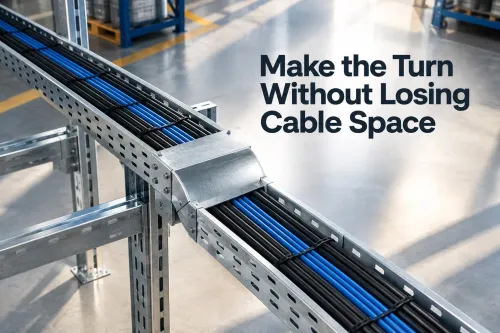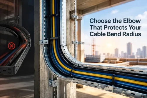
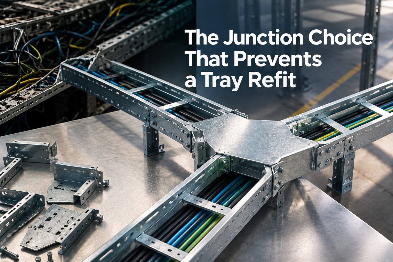
A tee and a cross solve different route problems: one branches a main run into two paths, while the other creates a four-way intersection. You will be able to select the right fitting, check its dimensions and orientation, plan supports and cable separation, and account for Delhi’s indoor, rooftop, monsoon and industrial conditions.
Key takeaways
- Choose a tee for one branch and a cross for two branching routes.
- Match tray width, side-rail height, rung spacing, and orientation before ordering.
- Recheck support spacing, cable fill, and bend radius at every junction.
- Specify finish, corrosion protection, drawings, and fit-up checks for Delhi exposure.
When a Delhi project needs a tee instead of a cross
Choose a tee when one incoming main route continues while two outgoing paths serve a single branch. A ladder tray tee joins three runs, making it suitable for a corridor turning into two service zones, a plant room feeding two equipment areas, or a building-services floor branching toward adjacent risers.
A cross joins four runs. Use it at a four-way intersection or where one main route splits toward three destinations, such as an infrastructure corridor serving separate substations, a commercial building’s distribution routes, or an industrial plant with three process areas.
The extra arm also creates more cable congestion and leaves less room for pulling and future additions.
| Fitting | Route arrangement | Practical choice |
|---|---|---|
| Ladder tray tee | One incoming run and two outgoing paths | One controlled branch while the main route continues |
| Ladder tray cross | Four connected directions | Four-way intersection or three destinations from one main route |
The search phrase ladder cable tray tee cross in delhi usually concerns horizontal plan-route fittings, not a cover or junction-box accessory. Map every cable entry and exit point on the plan before ordering, then check the cable count and the largest cable’s bend radius at each outlet.
A ladder cable tray tee in Delhi must be sized for the branch bundle and its bend radius, not only the incoming tray width. A ladder cable tray cross in Delhi deserves selection only when all four directions have a real route requirement and enough installation space.
How route geometry determines the fitting type
Choose a horizontal tee or cross for a plan change, a vertical inside or outside bend for an elevation change, and a reducer only when the tray width changes.
| Option | Route change | Use it when |
|---|---|---|
| Horizontal tee | Same-level branch | One route continues and another splits off |
| Horizontal cross | Same-level four-way junction | Four connected directions need tray space |
| Vertical inside or outside bend | Change in elevation | The route rises or drops and needs dedicated support and cable clearance |
| Reducer | Width transition | The cable volume changes along the route |
| Field-fabricated junction | Non-standard geometry | No standard fitting satisfies the route, bend radius, access and finish requirements |
A ladder cable tray tee in Delhi still needs checking against the section drawing. A horizontal branch that looks clear in plan can strike a beam, duct, pipe, ceiling or maintenance path when its elevation is shown. Review both drawings before approval.
Specify cable tray branching fittings as parts of one tray family, not by name alone. Match the tee or cross with the straight tray’s splice plates, bolts, covers, dividers, side rails and support hardware; mixed systems can leave incompatible holes, bonding paths or load data.
Use field fabrication only after this comparison. Welding and cutting introduce weld inspection, exposed cut edges, dimensional checks and zinc repair obligations, especially for galvanised steel. Confirm the finished junction still allows cable pulling, future access and the required bend radius.
The dimensional and orientation checks that prevent a bad fit
Reject the tee or cross if its geometry does not match the straight tray and the cable route. For a ladder cable tray tee cross in Delhi, verify these physical details before acceptance:
- Tray width and usable inside width
- Side-rail height, flange profile and cross-member spacing
- Material thickness and splice-hole pattern
- Finish, including galvanised or painted surfaces
- Stated compatibility with the straight tray, splice plates, bolts, covers and dividers
| Check | Evidence to match | What goes wrong |
|---|---|---|
| Main route | Incoming arm shown on the approved drawing | A mirrored fitting reverses the installation |
| Branches | Every outlet and branch direction identified | Cables turn toward a wall or blocked service zone |
| Supports | Support points and overall length shown | Existing supports shift or leave the fitting unsupported |
| Clearance | Throat and outlets accommodate the largest cable bend radius | A same-width branch forces a sharp cable turn |
Require a dimensional drawing or approved submittal showing the main-run direction, branch direction, overall length, usable inside width and support points. Check the largest cable’s bend radius through the throat and each outlet; matching nominal widths does not prove adequate clearance.
Before lifting the fitting, place it on the floor or compare it with the plan. Confirm which arm receives the incoming route, where each branch exits, and whether cable entry and exit remain accessible for pulling and future additions.
Inspect splice hardware and contact surfaces. Paint, heavy galvanising or field damage can interrupt electrical continuity unless the specified bonding arrangement removes the coating at the connection. Ensure the cable tray branching fittings belong to one verified tray family.
How load, support, fill and bend radius change at the junction
A tee or cross needs its own structural and cable-layout check; its straight-tray load rating is not transferable. The junction changes the load path, introduces concentrated loads and reduces usable space at the throat.
1. Obtain the manufacturer’s separate fitting load table. Check cable weight per metre, installation span, support spacing and concentrated loads at the junction. Place supports close to the fitting, branch throat and outer arm according to the tested system. Do not leave a long unsupported projection because adjacent straight lengths are supported.
2. Calculate cable fill in every outlet, not only the incoming route. A cross can congest four directions and leave too little pulling space for additions. Check whether power, control, instrumentation and data cables need separate trays, spacing or internal dividers for heat management and electromagnetic compatibility.
3. Verify the minimum bend radius before pulling. Check large power cables, single-core conductors, fibre-optic cables and communication cables at the throat and through every outlet; a same-width branch can still force an unacceptable turn. Add internal supports or dividers where cable weight, route separation or bend control demands them.
4. Treat cable tray branching fittings as part of the earthing design, not as automatic protective conductors. Painted, heavily galvanised or field-cut surfaces can interrupt continuity across splice points. Use the specified bonding arrangement, and do not count the tray as a protective conductor unless the project explicitly approves tray bonding and continuity.
A ladder cable tray cross in Delhi deserves this scrutiny before selection, especially where four routes converge. The same applies to any cable tray branching fittings specified by name without load, fill and bend-radius evidence.
What Delhi exposure and supplier checks belong in the specification
A ladder cable tray tee in Delhi or ladder cable tray cross in Delhi must be finished for the exposure, not labelled “Delhi” and left at that.
Indoor plant rooms and covered basements may suit pre-galvanised steel; open rooftops and monsoon-exposed routes deserve hot-dip galvanising after fabrication, while chemically polluted industrial sites may require stainless construction after compatibility review.
| Option | Suitable exposure | Check before approval |
|---|---|---|
| Pre-galvanised steel | Dry indoor plant rooms; protected basements | Confirm cut edges, welds and drilled areas receive zinc-repair coating |
| Hot-dip galvanised after fabrication | Rooftops and wet-dry monsoon routes | Confirm coating specification, drainage and treatment of field cuts |
| Stainless steel | Chemically polluted industrial sites | Confirm grade, fastener compatibility and resistance to the actual chemicals |
On a rooftop, reject a horizontal junction that forms a low pocket for water, debris or construction dust. Provide drainage, and keep water-sensitive cables out of areas that remain wet. Require the supplier to state material, coating, thickness, fitting load data, support assumptions, splice hardware, bonding method and zinc-repair treatment.
D And D Metal can help coordinate widths, finishes and supports, but approve drawings, samples and test data against your specification.
- Route drawing
- Fitting orientation and dimensions
- Cable schedule and bend radius
- Load table and support layout
- Separation plan
- Corrosion finish
Related products
 | cable tray Cable Tray Ladder Horizontal Cross A cable tray ladder horizontal cross is a type of cable management system that allows for the intersection of horizontal runs of cable trays. View product → |
 | Ladder cable tray Cable Tray Ladder Vertical Elbow Down A cable tray ladder vertical elbow down is a component used in cable management systems. View product → |
Frequently asked questions
When does a Delhi project need a ladder cable tray tee instead of a cross?
Use a tee when one incoming main route continues while one branch route leaves it. Use a cross when four tray runs meet and two branch routes leave the junction.
How do route geometry and orientation determine the fitting type?
Map the plan and elevation views first, then identify which runs continue, turn, rise, or drop. The fitting must match the tray width, side-rail height, and the direction of each connected run.
What dimensional checks prevent a bad ladder tray fitting?
Check tray width, side-rail height, rung spacing, connection-hole pattern, splice-plate position, bend direction, and whether the fitting is right-hand, left-hand, horizontal, vertical, or adjustable.
What changes at a ladder cable tray tee or cross junction?
Recheck cable fill, loading, support spacing, fixing strength, and the minimum bend radius because cables change direction and the junction adds concentrated weight.
What supplier and exposure details belong in a Delhi cable tray specification?
State the required material and finish, installation environment, dimensions, load basis, drawings, delivery scope, inspection documents, and confirmation that the tee or cross fits the specified tray system.
Related products
 | Ladder cable tray Cable Tray Ladder Horizontal Tee A cable tray ladder horizontal tee is a structural component used in cable management systems. View product → |
 | Perforated type cable tray Cable Tray Perforated Horizontal Cross A perforated horizontal cross for cable trays is a connector used in cable management systems. View product → |
 | cable tray A cable tray ladder reducer is a component used in electrical and networking installations to transition between different sizes of cable trays. View product → |
 | Cable Tray Perforated Type Cable Trays are a popular choice for supporting and managing electrical wires in various installations. View product → |
Keywords