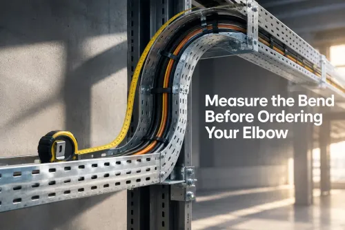
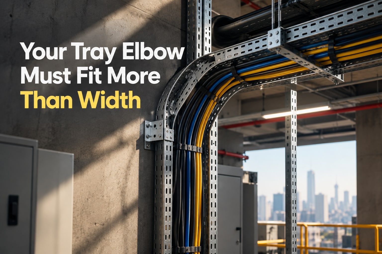
A vertical tray route fails when the fitting direction, bend radius, interface dimensions, cable load, or site clearance is guessed instead of measured. By the end, you will be able to read the route in plan and elevation, choose the correct transition, prepare a procurement drawing, and inspect the installed bend.
Key takeaways
- Read the route in plan and elevation before selecting an elbow.
- Match the elbow to tray type, width, height, radius and connection pattern.
- Check cable bend radius, fill, segregation and vertical load as one design.
- Inspect continuity, access and fire-rated penetrations after installation.
Read the route in plan and elevation before choosing the fitting
Start with the tray centreline, not the fitting name. In plan, a direction change across the floor needs a horizontal elbow; in elevation, a rise needs an elbow up and a drop needs an elbow down.
| Option | What it means | When it applies |
|---|---|---|
| Vertical elbow up | Turns the tray to a higher elevation | The outgoing run rises |
| Vertical elbow down | Turns the tray to a lower elevation | The outgoing run falls |
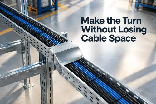
| Horizontal elbow | Changes direction across the floor | The route turns left or right in plan |
| Offset | Moves a parallel run sideways or vertically | A beam, pipe, or structural obstruction blocks the straight path |
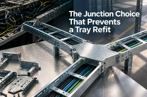
| Site-fabricated transition | A measured, reinforced custom change | No standard radius, angle, or connection clears the obstruction |
Stand at the cable-entry side and trace the cable path in its direction of travel. Mark up when the outgoing tray rises and down when it falls; this is the first control for a cable tray elbow down in delhi or a cable tray elbow up in delhi.
A common vertical elbow may rotate during installation, while another system uses handed fittings, so a catalogue photograph cannot confirm orientation.
Show the incoming and outgoing elevations, bend direction, viewing side, centre-line radius, support points, segregation, access clearance, and splice locations on the drawing. For a fabricated transition, add exact dimensions and reinforcement details for approval before manufacture.
Match the elbow to the tray, not just its nominal width
Before ordering, match the elbow to the tray’s actual geometry, not its nominal width. Record these dimensions on both drawings:
| Dimension | Existing tray | Elbow to confirm |
|---|---|---|
| Usable width | Clear cable width | Internal width through the bend |
| Outside width | Overall tray width | Overall elbow width |
| Side-rail height | Rail height | Rail height and profile |
| Material thickness | Sheet thickness | Sheet thickness and finish |
| Centre-line radius | — | Radius and tangent lengths |
| Straight section length | Available run | Elbow tangent length |
| Bend angle | Required change | Actual angle, not “90 degrees” |
| Connection-hole pattern | Hole spacing and slots | Matching holes, slots, and orientation |
Check whether the elbow fits inside the straight tray width or overlaps the tray’s outside faces. Compare its internal dimensions with the existing tray: side rails, splice plates, fasteners, and the curved throat reduce clear space, so a 300 mm tray does not provide 300 mm of cable width throughout the bend.
Ask for a dimensional drawing showing the centre-line radius, tangent lengths, elevations, and joint locations. Confirm the coupler position, splice-plate type, bolt diameter, slot orientation, washer clearance, and whether installers can tighten and inspect bolts after placement.
For a perforated cable tray vertical elbow in Delhi, list the width, side height, finish, thickness, radius, angle, and joint details on the purchase schedule. Confirm whether couplers, splice plates, bolts, bonding hardware, and support points are included or separately specified.
Calculate cable radius, fill, segregation, and vertical load together
Prove the bend by checking manufacturer radius, actual fill, segregation, and elbow loads as one route calculation.
- Obtain the minimum bending radius from each manufacturer’s data sheet for power, control, instrumentation, fibre-optic, and communication cables. Check the inside path, where the radius is smallest, and the outside path, where cables travel farther. A nominal 90-degree elbow passes only when its complete transition preserves every specified radius.
Give special attention to large single-core power cables and fibre-optic cables.
- Calculate fill from each cable’s actual outside diameter and the project specification’s fill rule. Do not use tray width alone: side rails, splice plates, fasteners, and the curved throat reduce usable space.
Reject any arrangement that forces cables into the throat, crushes lower layers under tightly stacked cables, or uses ties tight enough to reduce the bend radius.
- Confirm whether power, control, instrumentation, intrinsically safe, fire-alarm, and communication circuits require separate trays or physical segregation. Perforations do not provide electromagnetic or safety separation.
- Read the tray load table for the selected span, then calculate vertical cable weight, pulling force, and concentrated load at the elbow. Provide independent support near the bend and at both exits; long vertical runs need cleats or riser supports at calculated intervals.
Select cleats and straps for the cable type and applicable short-circuit forces.
This proves whether a cable tray perforated vertical elbow for routing problems in Delhi will carry the cables without radius damage, congestion, or structural overload.
Resolve Delhi site constraints, materials, and protection before procurement
Survey the finished opening before ordering: beams, false ceilings, sprinkler pipes, HVAC ducts, façade lines, drainage paths, access clearances, and the actual elevations of adjacent tray runs can overturn the drawing choice. A catalogue 90-degree elbow may collide with a service or leave no room to tighten bolts.
1. Measure the conflict in plan and elevation. Choose a larger-radius elbow when space permits, a two-piece offset around an obstruction, a short riser between mismatched levels, or a revised tray elevation. Do not force cables through a tight throat.
2. Specify the complete support assembly for the exposure: tray, brackets, splice plates, bolts, washers, bonding parts, and support spacing. Pre-galvanized sheet receives zinc before cutting and forming; hot-dip galvanizing coats the fabricated assembly. Name the repair method for drilled, cut, or damaged areas.
3. Match the finish across the joint. A galvanized tray on painted brackets can corrode where water and dust collect. Check stainless steel, aluminium, galvanized steel, and copper combinations, then isolate dissimilar metals where the project specification requires it.
4. Send the supplier the measured width, side-rail height, radius, material thickness, hole pattern, drawing, cable schedule, load data, support arrangement, and site photographs. The installation drawing must show elevations, splice locations, support points, orientation, and clearance.
D And D Metal belongs in a comparison request when a Delhi project needs a fitting made to those measured conditions; “generic vertical elbow” leaves the decisive choices unresolved.
Related products
 | Perforated type cable tray Cable Tray Perforated Vertical Elbow Up A perforated vertical elbow up for a cable tray is a fitting used to change the direction of cable trays in a vertical orientation. View product → |
 | Perforated type cable tray Cable Tray Perforated Vertical Elbow Down A perforated vertical elbow down in a cable tray system is designed to redirect cable pathways in a vertical direction. View product → |
Inspect the installed transition for continuity, access, and special penetrations
Before cables enter the bend, verify that the installed transition matches the approved drawing and leaves a safe, inspectable cable path. Confirm the elbow orientation, centre-line radius, incoming and outgoing elevations, independent support points, splice locations, cable segregation, and access clearance.
Check the physical joint against the drawing:
- Position the couplers and splice plates as specified, with bolt heads and nuts accessible for inspection and tightening.
- Remove sharp edges, burrs, zinc buildup, and misaligned holes that could cut a cable jacket.
- Test tray continuity and protective bonding across the elbow and every splice. Paint, loose hardware, zinc deposits, or a splice plate fitted on the wrong side can increase joint resistance.
- Fit a dedicated bonding jumper across the joint when the project specification requires one; mechanical contact alone does not prove continuity.
- Keep power, control, instrumentation, intrinsically safe, and fire-alarm cables segregated wherever the drawing or electromagnetic-compatibility requirements demand it.
After pulling, measure the actual cable path against each manufacturer’s minimum bending radius. Check tie tension and confirm that cable weight is supported by the tray, cleats, or riser supports—not the elbow throat.
| Location | Required treatment | Do not assume |
|---|---|---|
| Fire-rated wall | Tested firestop system | The elbow provides fire resistance |
| Roof or exterior opening | Drainage, sealing, and IP/weather protection | Sealing perforations is enough |
| Cable path | Preserve heat dissipation and access | Closed perforations are harmless |
Frequently asked questions
How do you choose between a cable tray elbow up and elbow down?
Read the route in elevation: use an elbow up for a rise and an elbow down for a drop. Use a horizontal elbow when the direction changes across the floor plan.
What must match between a perforated vertical elbow and the cable tray?
Match the tray system, nominal width, side-rail height, bend radius, material finish, splice arrangement and connection-hole pattern. Nominal width alone is not enough.
What should engineers calculate before ordering a vertical cable tray elbow?
Calculate the cables’ minimum bend radius, tray fill, power-and-control segregation, cable weight and the support load at the transition. Check the elbow geometry against the manufacturer’s dimensions.
Which Delhi site constraints affect perforated cable tray elbow routing?
Check available headroom, shafts, beams, ducts, access routes, dust and moisture exposure, galvanizing or coating needs, delivery limits and fire-rated wall or floor penetrations before procurement.
Keywords