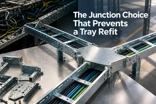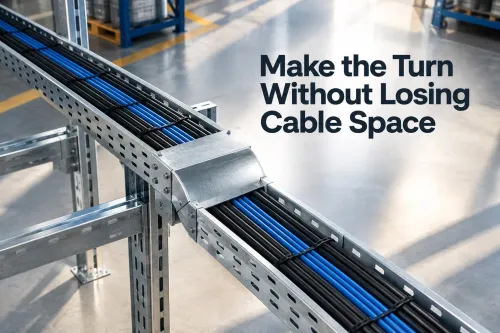
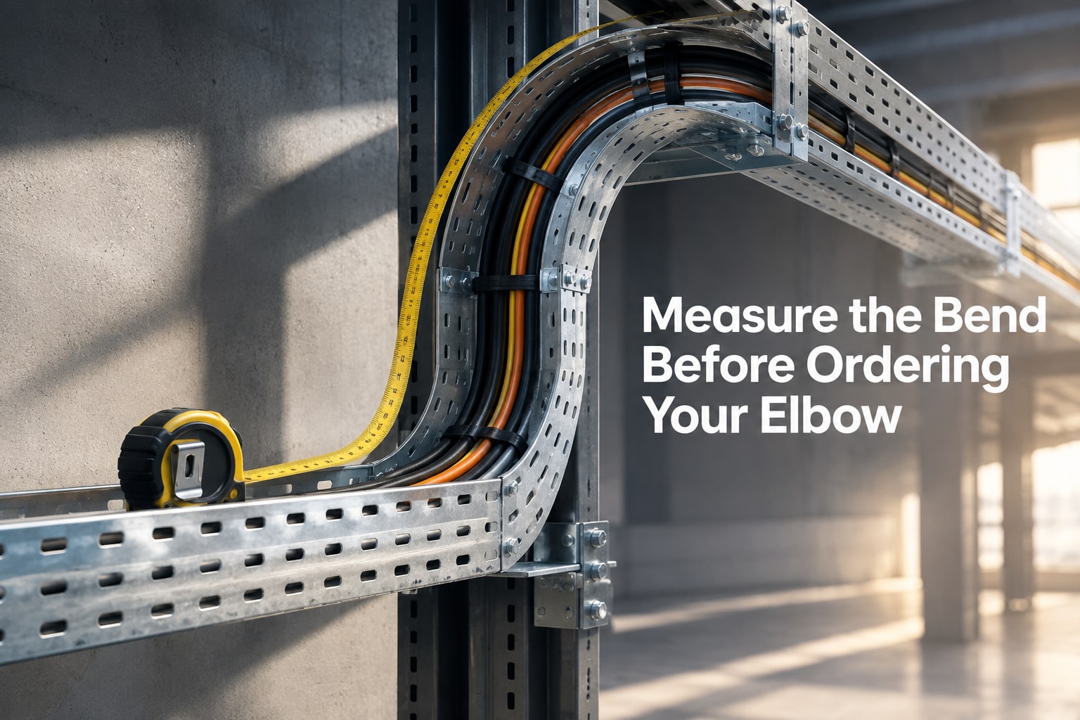
A beam, pipe run, equipment base, or floor-level change can make an approved tray route impossible to follow without a controlled vertical transition. By checking the obstruction, route geometry, cable bend limits, tray compatibility, and support arrangement in the right order, you can decide whether an elbow solves the problem or whether the route needs a different fitting combination.
Key takeaways
- Trace the centreline and record the obstruction before choosing up or down.
- Specify rise, run, radius, width, and angle instead of ordering by angle alone.
- Confirm tray width, height, perforation pattern, material, and finish compatibility.
- Check cable bend radius and add supports at the transition and joints.
Diagnose the route problem before choosing up or down
Trace the route from the existing tray centreline before selecting a fitting. Record the obstruction, its width and height, the required elevation change, and the final direction of travel.
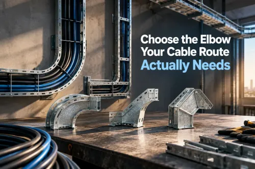
Perforated cable tray vertical elbows for route problems provide a controlled transition; they are not permission to force the tray around a beam, pipe, or equipment base.
Perforated tray vertical elbow up applies when the continuing tray run must rise from the approach run. Perforated tray vertical elbow down applies when the continuing run must fall.
| Option | Route meaning | Verification |
|---|---|---|
| Up | The continuing tray rises from the approach run | View the route in the direction of travel |
| Down | The continuing tray falls from the approach run | Confirm the destination centreline is lower |
| Neither | The route does not match the fitting geometry | Use a straight section, two fittings, or another angle |
Inspect the route before ordering:
- Check the space above and below the tray, clearance from pipes and structural steel, and room to install splice plates and supports.
- Allow space to pull cables through the transition without pressing them against the inside throat or side rails.
- Mark the centreline of both adjoining tray runs on the structure or floor.
- Compare the marked lines with the elbow angle. If they do not meet at a true 90-degree change, do not assume a nominal 90-degree elbow will fit.
Confirm the direction using the installed route, not a catalog photograph. A fitting that looks correct in isolation can have the wrong sweep, handed perforation pattern, or splice-hole orientation. Treat the elbow as a measured route recovery, not a shortcut around an obstruction.
Measure the bend geometry instead of ordering by angle alone
Measure the route in three dimensions before ordering perforated cable tray vertical elbows for route problems: record the elevation difference between the approach and destination tray centrelines, the horizontal offset, and the clearance available around the fitting.
Mark both centrelines on the structure, then confirm the finished elevation after allowing for the tray floor, side-rail height, splice plates, and support hardware.
Record the inside bend dimension and the outside sweep dimension. The continuing tray may sit inside or outside the angle formed by the two runs, and that choice changes whether the fitting clears a beam, pipe, or neighbouring service.
| Geometry | What to measure | Why it matters |
|---|---|---|
| Inside bend | Radius or throat dimension on the inside of the turn | Prevents the tray or cables from entering an obstruction |
| Outside sweep | Fitting’s maximum outer projection | Confirms clearance from nearby services and steelwork |
| Route angle | Actual angle between adjoining tray centrelines | Shows whether one elbow is suitable |
| Finished elevation | Tray floor, rail, plates, and supports included | Prevents the destination run from ending too high or low |
A 90-degree elbow fits only when the runs meet at a true right angle and its sweep clears surrounding services. For a smaller angle, use a matching fitting or combine fittings with a short straight length; never bend a standard elbow on site.
Locate every support on both adjoining runs and mark a support position near the transition. Check bolt-tightening access and cable-placement space without exceeding the cable manufacturer’s pulling-tension or sidewall-pressure limits. Request a dimensioned supplier drawing showing radius, width, height, overall length, splice-hole positions, and which direction “up” or “down” represents.
Confirm tray compatibility before requesting a vertical cable tray fitting in Delhi
Compatibility requires more than a matching tray width. Compare the existing straight tray with the proposed elbow before ordering; a 300 mm tray with a different side-rail profile or splice-hole pitch may need different plates and hardware.
| Check | Match before ordering | What goes wrong if it differs |
|---|---|---|
| Width and height | Tray width, side-rail height, and rail profile | The elbow sits proud, narrow, or cannot align |
| Construction | Material, thickness, perforation pattern, and flange shape | Holes, edges, or load capacity do not correspond |
| Joint layout | Splice-hole pitch and position | Plates or bolts miss the holes |
| Finish | Pre-galvanized, hot-dip galvanized, aluminium, stainless steel, or painted steel | Corrosion protection and cut-edge treatment become unsuitable |
Confirm whether the system uses bolted splice plates, internal connectors, external connectors, or a manufacturer-specific joint. Specify inside or outside bend geometry, bend radius, angle, elbow direction, and both connecting tray sizes; a perforated tray vertical elbow up and a perforated tray vertical elbow down may have handed perforations or connector layouts.
Include these items in your request for a vertical cable tray fitting in Delhi:
- A marked route sketch with measured dimensions and final elevations
- Photographs of the existing joint, rail profile, holes, and finish
- Cable types, estimated load, support spacing, and required bend clearance
- The project specification or named standard
D And D Metal can review those measurements to match a fabricated or stocked fitting instead of quoting a visually similar elbow.
Approve the elbow against the cables, not only the tray
Approve the elbow only after the largest and least-flexible cable in the route passes its bend and space checks. For perforated cable tray vertical elbows for route problems, obtain the manufacturer’s minimum static bend radius and installation bend radius for every cable type involved.
| Cable type | Ask for | Approval check |
|---|---|---|
| Power, control, instrumentation | Static and installation bend radii | Compare each limit with the elbow’s actual inside radius |
| VFD and medium-voltage | Static and installation bend radii, pulling limits | Use the larger stated limit and check sidewall pressure |
| Data, armoured, and fibre-optic | Static and installation bend radii, pulling limits | Confirm the jacket, armour, or fibre construction is not forced against the throat |
A nominal 90-degree tray angle does not establish a safe cable bend. The tray changes direction, but each cable follows its own curve through the fitting throat.
Check the elbow for these failure points:
- Side rails, splice plates, perforation edges, and the inside throat pressing into a cable
- Reduced usable area, cable stacking, loss of spacing, or cables lifting from the tray floor
- Migration toward the inside radius and concentrated side loading on the bend
Calculate bend fill separately from straight-run fill. A tray that has spare capacity on the straight section can overcrowd at the elbow.
Plan the pulling direction before installation. Use rollers or a controlled pulling method for long or heavy runs, and follow the cable manufacturer’s pulling-tension and sidewall-pressure limits. Add cleats or hold-downs only when their design suits the cable construction and fault forces; perforations do not replace a restraint calculation.
Design the transition support, joints, and finish as one assembly
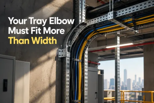
A stable transition depends on treating the elbow, supports, splice plates, cables, and finish as one load-bearing assembly rather than as separate parts.
1. Support both adjoining horizontal or vertical runs, then place a support near the elbow within the tray manufacturer’s permitted span. Calculate the combined weight of the elbow, splice hardware, installed cables, and future allowance; two optimistic brackets must not carry a heavy riser.
2. Keep splice joints out of unsupported locations when the system instructions prohibit them. Provide independent riser support when the vertical run or cable load concentrates weight on the elbow, instead of transferring that load through the adjoining tray.
3. Check vertical cable movement at the transition. Cables can migrate toward the inside radius, lift from the tray floor, or impose side loading, so add cleats, hold-downs, or other restraint when the cable construction and fault-force design require it.
4. Preserve electrical continuity across every joint. Paint, galvanizing irregularities, washers, and field drilling can interrupt the bonding path; install the specified bonding jumper or continuity hardware when the design requires it.
5. Protect every cut or drilled galvanized edge with a repair system compatible with the original finish, especially outdoors or in humid, coastal, chemical, or washdown areas.
Before pulling cable, dry-fit the perforated tray vertical elbow up or perforated tray vertical elbow down, verify elevation and clearance, tighten the joint, remove sharp edges, and confirm the elbow is not a walkway or access platform.
Frequently asked questions
How do you diagnose a route problem before choosing a vertical elbow?
Trace the existing tray centreline, then record the obstruction, its width and height, the required elevation change, and the final travel direction. Choose a perforated tray vertical elbow up when the route must rise, or a perforated tray vertical elbow down when it must drop.
What measurements are needed before ordering a vertical cable tray elbow?
Measure tray width and height, the required rise or drop, available horizontal run, bend radius, entry and exit directions, and the clearance around the obstruction. Do not select the fitting by angle alone.
How do you confirm a vertical cable tray fitting in Delhi will fit the existing tray?
Match the tray width, side-rail height, perforation pattern, material, coating or finish, joint design, and fastener locations. Request a dimensioned drawing before approving the fitting.
What must you check besides tray compatibility?
Check every cable’s minimum bend radius, fill and separation requirements, pulling access, support spacing, joint alignment, and the transition’s load path. The elbow and its supports must work as one assembly.
Keywords