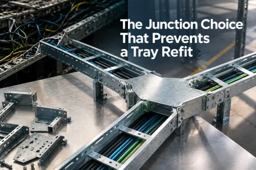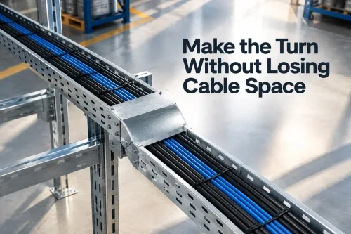

A vertical tray bend can look correct on a layout and still fail because it turns in the wrong direction, forces cables below their minimum bend radius, or lacks restraint for the vertical load. You will be able to read the route, verify the elbow’s geometry and interfaces, coordinate supports and bonding, and write a purchase description suited to the Delhi site.
Key takeaways
- Confirm up or down from plan, elevation, section, and route arrows.
- Match the elbow radius to the largest cable’s minimum bend radius.
- Specify supports, restraints, bonding, movement allowance, and tray dimensions.
- State material, finish, load, angle, radius, and direction on the purchase order.
Read the route mark-up before choosing up or down
Resolve the fitting direction from the plan, elevation, section, and route arrows before selecting an elbow. A ladder tray elbow down normally changes a horizontal run into a descending vertical run; an elbow up rises from the horizontal run.
| Option | Drawing meaning | Check before approval |
|---|---|---|
| Vertical elbow down | Horizontal tray turns into a descending run | Confirm the next straight section is below |
| Vertical elbow up | Horizontal tray turns into a rising run | Confirm the next straight section is above |
| Inside vertical bend | Tray turns through the inside of the route bend | Confirm the inside radius and cable path |
| Outside vertical bend | Tray turns around the outside of the route bend | Confirm restraint and available clearance |
| Horizontal elbow | Tray changes direction on the same level | Do not order it as a vertical fitting |
Do not rely on supplier naming alone; manufacturers use these terms inconsistently. Confirm which tray side is inside the bend and where the next straight section sits. A request for ladder tray elbow down in Delhi can otherwise produce the wrong orientation.
For a 90-degree route, state the exact vertical elbow orientation. For another angle, use a segmented, purpose-made non-standard, or adjustable arrangement only after checking bend radius, splice positions, cable support, and installation space.
Attach a dimensional sketch to the purchase order showing:
- Direction of turn and angle
- Centre-line radius, tray width, and side-rail height
- Elevations of both straight sections
- Inside or outside bend designation and route arrows
That drawing removes ambiguity before fabrication.
Match the elbow to the tray and the cable bend radius
Match the elbow to the complete tray system, not the tray width alone. Compare each vertical ladder cable tray fitting with the straight sections for these dimensions:
| Check | Required match | Failure if ignored |
|---|---|---|
| Usable width and side-rail height | Same clear cable space and rail depth | The bundle or cover line may foul the bend |
| Rung spacing, flange profile, and material thickness | Same support pattern and structural section | Cables lose support or the fitting carries a different load |
| Joining-hole pattern | Aligned holes on both straight sections and the elbow | Site drilling weakens the connection and damages the finish |
Confirm that connector plates, splice plates, bolts, washers, and fasteners fit the supplied holes before delivery. For a ladder cable tray vertical elbow in Delhi, calculate the cable path rather than accepting a same-width fitting.
The inside radius controls minimum bend-radius compliance. Use the largest minimum radius stated by the cable manufacturer for every installed power, medium-voltage, single-core, armoured, control, instrumentation, fibre-optic, or data cable. A bundle can fit the tray width and still be too tight at the elbow; restrain the outside of the bend against separation and movement.
For single-core AC cables, preserve the specified phase formation and spacing through the bend. Use non-magnetic cleats where required, and avoid ferromagnetic clamps or magnetic loops that can increase induced or circulating currents. If the route uses segments, verify the radius across every segment, not only the first and last.
Coordinate support, restraint, continuity, and movement
The elbow and the cables need separate support decisions at the direction change. Confirm the fitting’s working load and support span independently; a horizontal straight-tray loading table does not automatically apply to a vertical elbow.
1. Show a support immediately before and after the elbow, then check whether the cable mass or prospective short-circuit forces require a radius saddle, divider, cleat, clamp, tie, or rung-mounted support. Select spacing from the cable diameter, mass, fault forces, and cable manufacturer’s installation instructions.
2. Do not treat a tray rung as a vertical cable cleat unless the design and manufacturer confirm it. Unsupported cables can slide downward, overload the lower bend, and pull on terminations.
Heavy or stiff cables need a nearby pull point, straight approach length, rollers during installation, and a support immediately before or after the fitting.
3. If the tray forms part of the protective bonding path, state the splice bonding method and verify continuity across every joint. Check the elbow, connector plates, splice plates, fasteners, and every expansion joint; coated metal-to-metal contact alone is not proof of continuity.
4. Coordinate outdoor movement rather than locking every joint rigidly. Use ΔL = αLΔT: carbon steel at approximately 12 × 10⁻⁶/K moves about 36 mm over 50 m for a 60°C temperature change. Provide expansion splice plates, bonding jumpers, and supports that allow the calculated movement without losing restraint.
Check the pull route before approval. A fitting that satisfies the cable radius but lacks handling space or positive restraint can fail during installation or service.
Choose ladder construction against the project exposure
Keep the open ladder form only where the bend and the full route suit large, heat-producing cables. A ladder type cable tray for vertical elbow in Delhi is a poor choice when frequent changes need enclosed protection or the elbow cannot provide positive restraint.
| Option | What it provides | When it applies |
|---|---|---|
| Ladder tray | Ventilation and access | Large power cables with controlled dust and falling-object exposure |
| Perforated or solid-bottom tray | Continuous support and side containment | Small loose cables, dust, falling objects, or a required closed bottom |
| Raceway or fire-rated system | Enclosure and tested separation | Project specifications requiring fire performance or controlled fire separation |
| Field-fabricated mitred bend | A designed custom transition | Only after engineering the radius, strength, edges, coating, and access |
Specify the actual Delhi exposure: indoor or outdoor location, industrial emissions, traffic pollution, condensation, wash-down, nearby drains, cooling towers, and chlorides. Do not assign one corrosion category to the whole city.
Treat a mitred bend as fabrication, not a shortcut. Verify:
- Cable radius at the inside of the bend and restraint against movement at the outside.
- Sharp edges, weld quality, splice strength, and inspection access.
- Coating repair after cutting, drilling, or welding.
- Cleats, clamps, ties, or rung supports that prevent cable weight sliding into the lower bend.
Use a raceway or fire-rated system when the specification demands enclosure; use solid-bottom containment when an open ladder would expose cables to contamination or impact.
Write a purchase description that prevents a wrong elbow
Put the engineering decision into the schedule and dimensional drawing, not just the description “vertical ladder cable tray fitting.” A ladder cable tray vertical elbow in Delhi must identify the route direction, bend angle, centre-line radius, tray width, usable width, side-rail depth, rung spacing, flange profile, joining-hole pattern, load class or working load, support arrangement, splice-plate type, bolts, washers, fasteners, and cable cleat or divider requirements.
1. State whether the turn is up or down, and show both connected straight sections, elevations, inside/outside bend, cable clearance, and required bend radius. Attach the approved route sketch to prevent a supplier interpreting “elbow down” as a different fitting.
2. Specify the material and finish: hot-dip galvanized after fabrication, pre-galvanized, electro-galvanized, aluminium, or stainless steel. For outdoor work, name ISO 1461 and its acceptance basis, coating thickness or mass, surface preparation, treatment of drilled and cut edges, and the approved zinc-rich repair system, such as ASTM A780-compliant repair.
3. Before approval, obtain the manufacturer’s elbow drawing, loading data, cable-radius confirmation, continuity detail, and expansion-joint arrangement. D And D Metal can review the straight-tray interface, exposure, supports, and customer dimensions together, avoiding an isolated generic fitting.
The purchase order must name the exact fitting, fastening set, support detail, and cable restraint arrangement.
Frequently asked questions
How do you determine whether a ladder tray elbow goes up or down?
Read the plan, elevation, section, and route arrows together. A ladder tray elbow down changes a horizontal run into a descending vertical run; an elbow up creates a rising vertical run.
How do you match a vertical ladder tray elbow to the cables?
Confirm the tray width, side-rail height, fitting angle, and inside radius. The elbow’s inside radius must accommodate the largest cable’s specified minimum bend radius without forcing or kinking the cable.
What must be coordinated around a ladder tray vertical elbow?
Coordinate trapeze or cantilever supports, vertical restraints, bonding across joints, access for cable installation, and allowance for thermal or building movement.
What details should a purchase description include for a ladder tray elbow?
State the direction, angle, width, side-rail height, inside radius, material, finish, load requirement, splice hardware, support requirements, and cable route reference.
Keywords